Alignment for MonoCL and ChromaCL
Insert the collection mirror
To use the MonoCL™ or ChromaCL™ systems, insert the collection mirror into the scanning electron microscope (SEM) chamber manually:
-
Ensure it is safe to insert the collection mirror; the sample should be at a safe working distance, and no other detector should occupy the space needed for the collection mirror.
-
Set the SEM to a magnification of ~100x.
-
While viewing a secondary electron image, slowly insert the collection mirror so that its electron beam aperture appears central in the image.
Set the sample at the correct working distance
 For the cathodoluminescence (CL) system to operate efficiently, adjust the SEM stage location (Z-axis) so the sample is set to the focal point of the collection mirror.
- MonoCL and ChromaCL systems – Refer to the user guide to manually perform this operation.
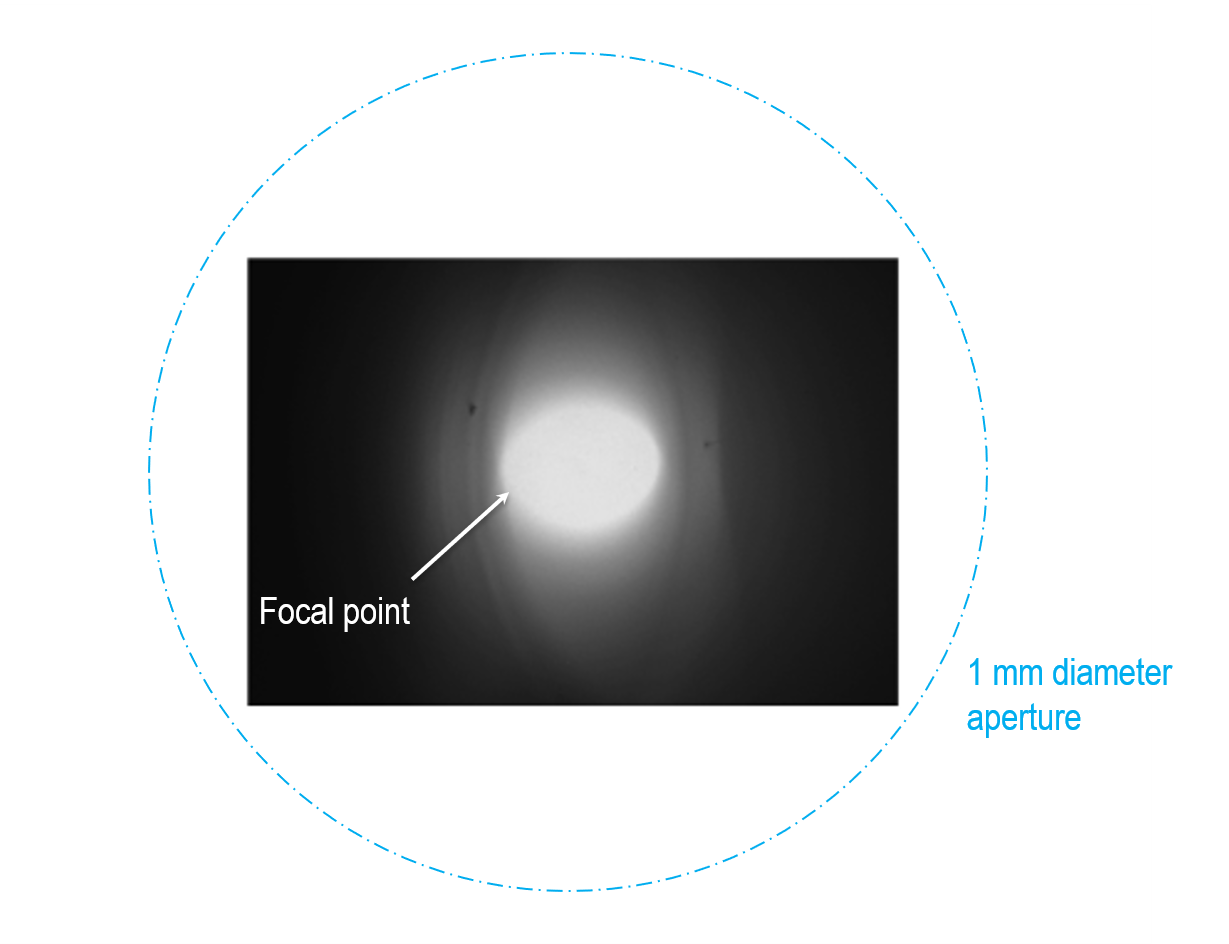
- Systems using the standard 10 mm tall collection mirror – The optimum distance is 0.95 – 1.05 mm below the bottom surface of the mirror. It may require fine adjustment to optimize the position based on the feedback from the CL signal.
The image shows the optimum settings when observing a clearly defined optical focus (hot spot or sweet spot). Note that the focus spot appears more like a crescent when the sample is not at the focal position.
Center the collection mirror
To align the CL system to the SEM's electron beam, locate the mirror focal point at the center of the SEM field of view. The precise location of this can be challenging to determine and track as you cannot directly observe the focal point of the collection mirror. However, you may use the hot spot (see above) and adjust the mirror's position (in the x- and y-axis) to align the hot spot to the center electron beam scan (center of the image). Note that using an electronic image shift will cause an apparent shift in the mirror position. This is useful for fine alignment of the collection mirror but should not be used during CL analysis in case of inadvertent misalignment of the CL and SEM systems.
Ready to go…
When all components are optimally aligned, the light reflected from the collection mirror forms a collimated beam bundle that is free space coupled to the optical components downstream. The alignment of the downstream optical components is optimal for a collimated beam. No user alignment of the optics is required.