Optimizing Emission Patterns
Alignment is key

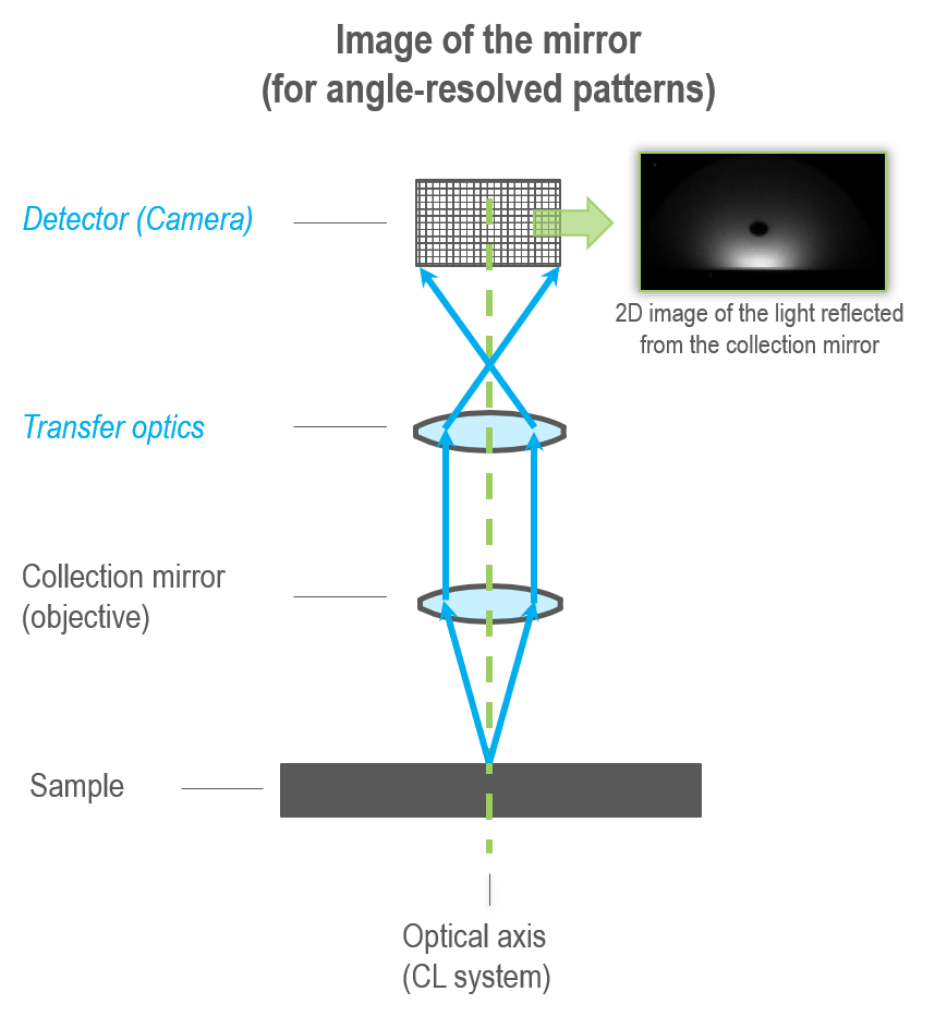
High-resolution, angle-resolved cathodoluminescence (ARCL) requires each pixel in the projected image to directly relate to an emission direction. Misalignment(s) in the optical system can easily destroy the pixel-direction relationship unless you use the specially designed transfer optics of the Monarc® Pro detector.
To learn more about the alignment of the Monarc, please click here.
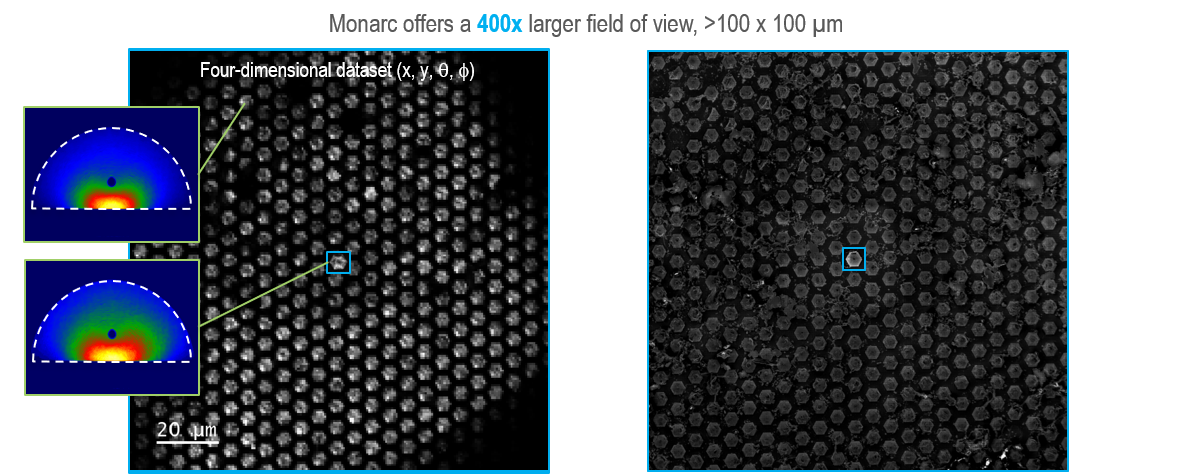
The alignment of the optical system remains critical. The Monarc Pro simplifies this process using an automated alignment algorithm combined with the largest field of view in the x-y plane and z-axis. Here, an angle-resolved spectrum image with a field of view in excess of 10,000 µm2 is shown, more than 400 times larger than with other systems.

Transformation into polar coordinates
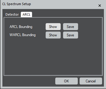
The software stores information about where the projected image last fell on the camera and uses this to transform the raw images into polar coordinates. In rare cases (such as the exchange of the collection mirror), it may be necessary to update the  software with a new image location. To do this, open the CL Spectrum Setup from the Setup icon in the CL palette, then select Show to see the ARCL or WARCL Bounding box for the appropriate data. Reposition the region of interest so the projected image falls precisely within the bounding box and click Save.