Collecting Emission Patterns
Acquire an emission pattern
There are two methods for collecting cathodoluminescence (CL) emission patterns: Angle-resolved (ARCL) and wavelength– and angle-resolved (WARCL) acquisition. During ARCL, each pixel in the captured image corresponds to a unique emission direction from the specimen (unless an optical filter is inserted into the light path). In contrast, WARCL collects a 3D data cube (λ,θ, Φ) and can be thought of as a stack of wavelength-filtered emission patterns or a (wavelength) spectrum recorded in every emission direction.
 Within DigitalMicrograph® software, an emission pattern may be captured using the ARCL Imaging technique:
- Position the beam on the sample region of interest using the Scan palette.
- Spot – Sets the beam at a stationary location on (or to avoid damage, off of) the specimen
- Focus – Scans a sub-region of the field of view
Ensure that the refresh rate of the scan is shorter than the exposure time of the emission pattern.
 Capture an emission pattern.
Angle-resolved
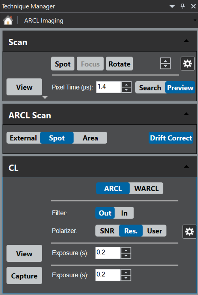
Set the mode to ARCL within the CL palette, then press View or Capture to collect an ARCL emission pattern. This will open two image displays within the View workspace, one showing the raw image projected from the back surface of the collection mirror and the other showing an emission pattern image transformed into polar coordinates.
- View – The image continually updates per the exposure time selected
- Capture – Records a single exposure, then opens the data and includes the SEM's electron beam location in a new workspace
- Optimization – Determines the read-out configuration of the detector
- SNR – High signal-to-noise
- Res. – High resolution
- User – User-defined binning and dark correction
The Monarc Spectrometer State palette also permits the insertion of an optical filter into the beam path (optional item).
See the Spectrum Imaging section for more information on collecting spatial– and angle-resolved emission patterns (4D data).
 Wavelength– and angle-resolved
In the ARCL mode, the emission pattern does not contain (or only limited) wavelength information. In that case, it measures the entire angular range in parallel without recourse to dispersing the light by wavelength.
In contrast, the WARCL mode selects a subset of the angular range and records the dispersed light by wavelength. It then serially scans the angular range to collect all available angular and wavelength information.
WARCL uses the same CL acquisition palette as ARCL.
- Position the beam on the sample region of interest using the Scan palette.
- Spot – Sets the beam at a stationary location on (or to avoid damage, off of) the specimen
- Focus – Scans a sub-region of the field of view
Ensure that the refresh rate of the scan is shorter than the exposure time of the spectrum.
- Capture wavelength-resolved emission patterns.
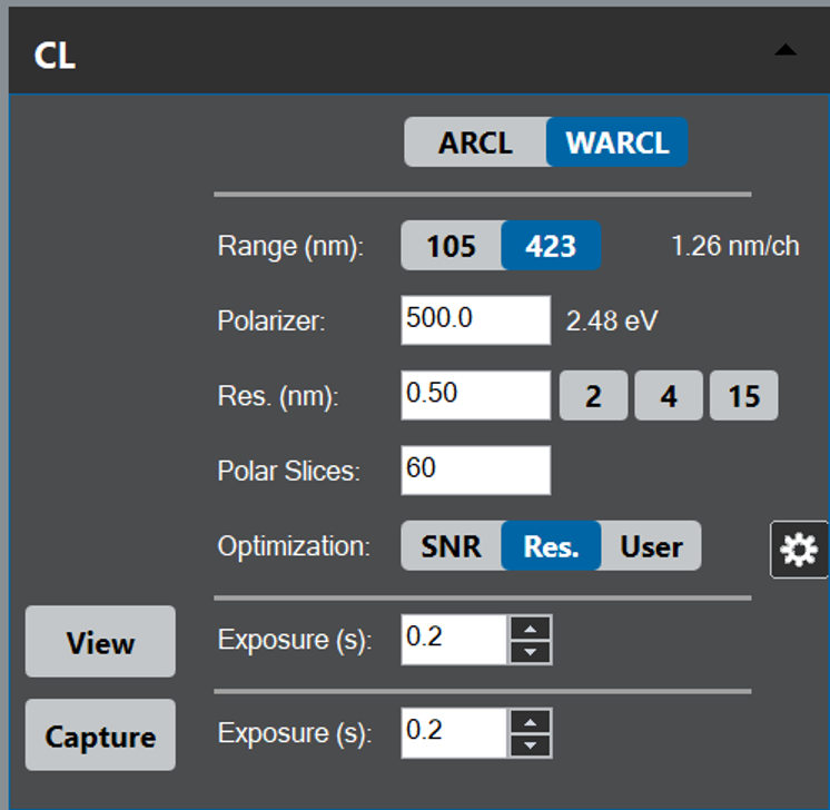
Within the CL palette, set the mode to WARCL, then press View or Capture to collect WARCL emission patterns.
The Monarc system collects a 2D image stack whose x-axis corresponds to wavelength—centered around the value defined in the WL (nm) entry—and y-axis angle-space θ', Φ.' The angle space in the raw image cannot be interpreted easily due to the complex geometry of the projected image and constitutes only a fraction of the total angular range. It records a series of angle-space (θ', Φ')–wavelength images, with the total angle-space captured serially. You can transform the final 3D (λ,θ', Φ') data cube to reconstruct wavelength-resolved emission patterns using the Remap WARCL Image item from the Monarc Remap menu. Standard tools such as the spectrum picker and slice tools are useful for displaying the emission pattern within a specified spectral range or extracting a spectrum from a specific emission direction.