Overview
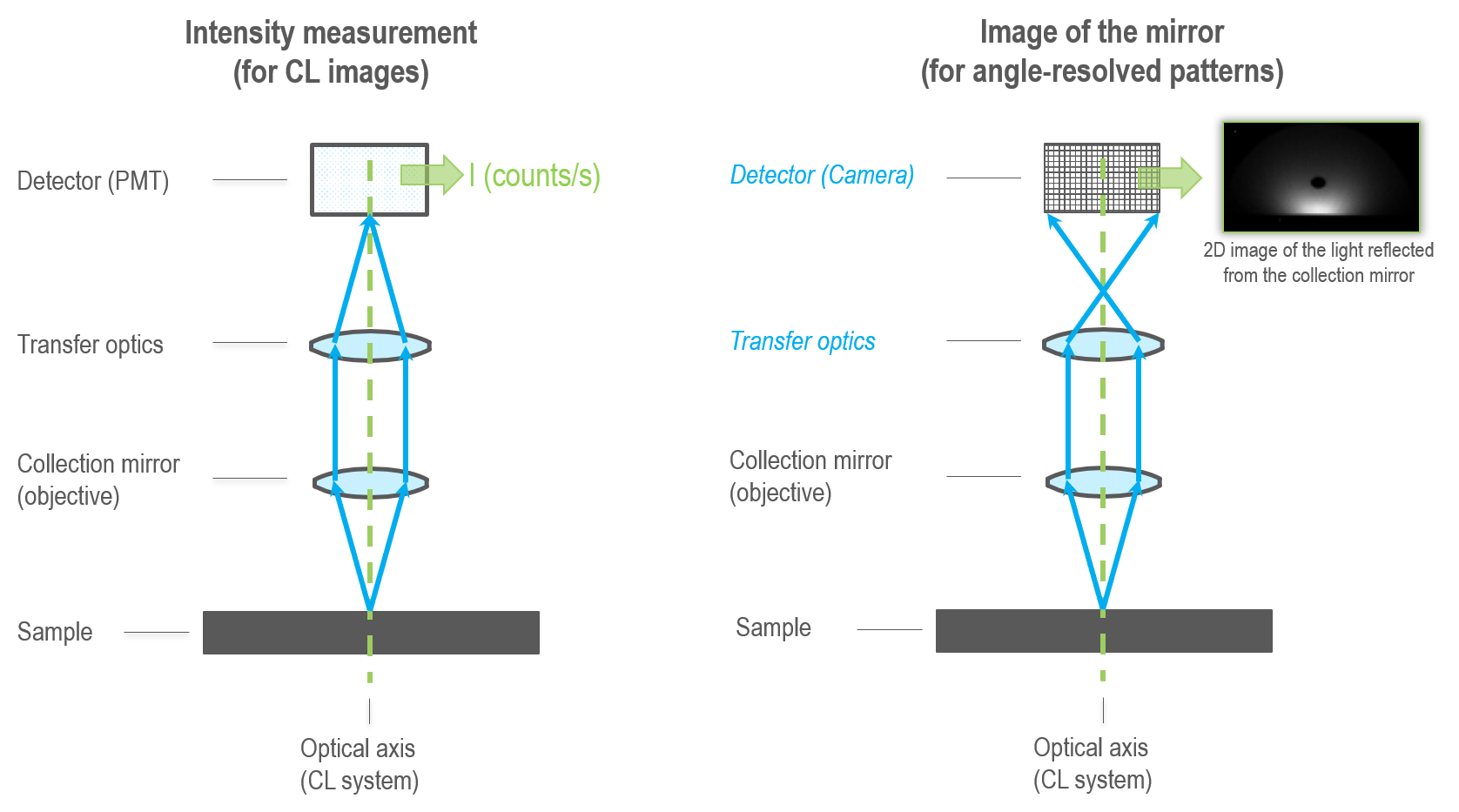
 In the angle-resolved cathodoluminescence (ARCL) mode, the direction in which a photon is emitted is determined. An objective lens or, more commonly, a collection mirror projects an image of the emitted light onto a pixelated detector, e.g., a camera. When an appropriate optical system is used, each pixel in the captured image corresponds to a unique emission direction from the specimen. The raw image is typically transformed into polar coordinates for display and interpretation.
The result of an angle-resolved measurement contains no wavelength or polarization information unless additional dispersion filtering is used (e.g., wavelength—and angle-resolved mode).
Angle-filtered information may be captured using an iris or a pinhole to select a specific (range of) angle(s). However, this particular acquisition mode's low resolution and highly serial naturehave limited its usefulness.
Sometimes referred to as Fourier imaging or momentum spectroscopy.
Data collection
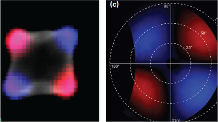
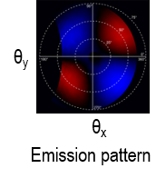 Emission pattern or angle-resolved emission pattern: The emission pattern is a plot of the direction in which photons are emitted from a specimen. It is typically presented in polar coordinates, where the emission direction is described by the azimuthal and zenith angles. A single emission pattern may be captured from a point or region of the sample exposed to the electron beam of the electron microscope.
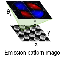 Emission pattern image or angle-resolved spectrum image: The electron beam is scanned across the specimen surface, and an emission pattern is recorded at each location, creating a hyperspectral (4D) data construct.
Uses
 |
Investigating the optical properties of nanophotonic materials far below the diffraction limit |