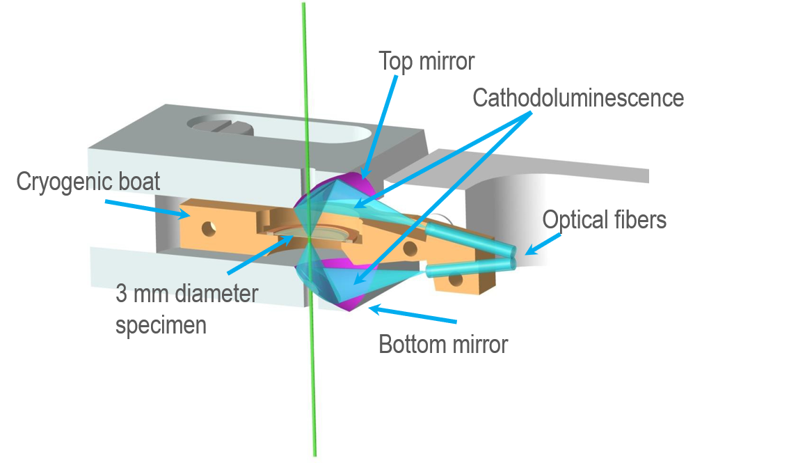
To collect the cathodoluminescence (CL) emitted from a sample, high numerical aperture (NA) mirrors are positioned above and below the specimen. Each mirror contains a small aperture that allows the primary electron beam to excite the specimen and for transmitted electrons to escape. Photons emitted from within a focal point of the collection mirrors are reflected and focused onto optical fibers that carry the signal out of the transmission electron microscope (TEM) column to analysis instrumentation.
A screw ring clamps the sample (3 mm diameter grid) into a small cradle to ensure it achieves good thermal contact.
The cathodoluminescence collection mirrors
The CL collection mirrors are manufactured to a precise mathematical form and are ellipsoidal. Ellipses are defined mathematical shapes with two focal points: one at the sample region of interest and the other at the optical fiber facet. The alignment of the two mirrors ensures each focus is co-aligned to be at the sample's region of interest. The light emitted from the mirror's focal point on the specimen is coupled very efficiently into the optical fibers.
You cannot adjust the CL collection mirrors to optimize the position at which light is collected efficiently from a sample because it degrades light coupling to the optical fibers. The only way to achieve this is by moving the specimen grid within the specimen cradle so that the region of interest coincides with the region from which CL is collected efficiently. An optical microscope and lightbox are available so that you can inspect this during the sample insertion into the sample cradle.
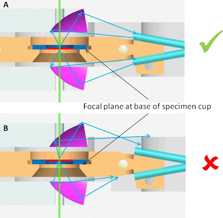
It is important to manufacture specimens so that the thin region of the specimen is approximately centered on the 3 mm grid. For thick samples or a non-standard 3 mm copper grid (e.g., silicon nitride membranes supported on silicon), it is essential to position the sample's region of interest within the focal depth of the system since there is a limited focal depth (z-direction). The focal plane of the mirrors is designed to be the face on which a thin specimen sits. Ensure that the orientation of thick specimens is such that the region of interest is placed against the bottom of the specimen cup. See Figure below.